
Table of Contents Water leak detection is designed to detect and repair leaks in pipes, equipment or building structures in
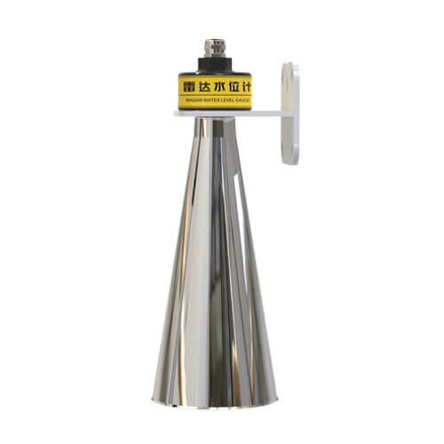
Radar Flow Meter
This radar flow meter uses a non-contact method to monitor water flow rate and water level. It is mainly composed of water flow meter and water level meter. The flow meter is used to collect the surface flow rate of the fluid and calculate the average flow rate of the water section through the model. The water level meter measures the water level and cross-sectional information to calculate the cross-sectional area of the flow, and uses the formula flow = average flow rate × cross-sectional area × correction coefficient to get the flow rate. The correction coefficient is calculated based on the standard value obtained from the actual measurement environment.
- Model: RS-RAD-N01-3-EX
- MOQ: 1 PCS
- Delivery date: within 24 hours
- Price:USD 545
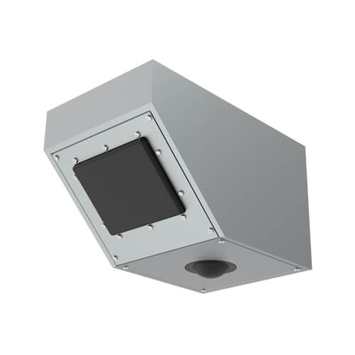
Radar Flow Meter View
Our radar flow meter uses the Doppler radar velocity measurement principle. When measuring the water surface, the radar flow sensor emits microwaves to the water surface, and the microwaves are absorbed and reflected when they encounter the water surface. Part of the reflected wave is received by the flow meter probe, and then converted into an electrical signal, which is processed by the measurement circuit and the Doppler frequency shift is measured. The water flow rate can then be calculated based on the signal processing algorithm. The radar water level meter uses FMCW modulation, with a triangular wave as the modulation signal.

| Power supply | DC 10-30V |
| Max. power consumption | 1.3W |
| Component temperature and humidity resistance | -40℃~+80℃, 0%RH~95%RH (non-condensing) |
| Measure flow rate frequencyfrequency | 24.00GHz |
| Flow rate range | 0.1 ~20m/s |
| Flow rate accuracy | ±2% |
| Flow rate resolution | 0.01m/s |
| Measure distance frequency | 76GHz~81GHz |
| Water level range | 0.1 ~ 65m (maximum range when measuring water level only) |
| Range accuracy | ±1mm |
| Range resolution | 1mm |
| Usage height | 0~20m |
| Protect class | IP67 |
Radar Flow Meter Installation
Select the installation site
The selection of the measuring channel section is directly related to the accuracy of the data. To ensure the accuracy of the results, the following conditions should be met:
1. There are no huge rocks blocking the water in the test channel section, no large whirlpools, turbulence, etc.
2. The water flow in the test channel section is stable and concentrated.
3. The test channel section needs to be hardened and the measuring section should be regular.
4. The test channel section should be kept smooth to prevent the accumulation of floating objects.
Install the radar flow meter in the middle of the channel or river or as close to the center as possible, with one side of the inclined surface facing the water flow direction.


Antenna beam range
The radar flow meter integrates a water level meter and a current meter. The water level meter antenna beam angle is 6×6°, and the radar antenna angle is 30×80°. When the water level meter illuminates the water surface, the illuminated area is similar to a circle. When the current meter illuminates the water surface, the illuminated area is similar to an elliptical area. As shown in the figure. An accurate understanding of the irradiation range of radar waves helps to choose a suitable installation location to avoid interference from branches on both sides of the river and floating debris in the water.
Installation height
Under the same conditions, the higher the installation height, the weaker the echo and the worse the signal quality. Especially for scenes with low water flow velocity, the ripples are small and more difficult to measure. At the same time, the area of radar wave irradiation will be larger. It is possible that the beam will irradiate the bank of the channel and be interfered by moving targets on the bank. If it is installed too low, it will not be conducive to anti-theft protection, so the recommended height for pole installation is 3-4 meters.
Notes
1. When installing the flow meter, the water level meter and the velocity meter radar must not be blocked, otherwise it will affect the measurement accuracy.
2. When installing the flow meter, try to ensure that the upper surface of the shell is horizontal and installed in the middle of the channel.
3. The velocity meter beam is recommended to face the incoming water direction, and the horizontal angle with the water flow direction is 0 degrees.
4. The velocity meter is only affected by dynamic targets. When the channel is hardened and there are no weeds or trees, even if the beam is irradiated on both sides of the channel, it will not affect the measurement data.
Radar Flow Meter FAQs
Radar flowmeter and ultrasonic flowmeter are two commonly used technologies in modern industrial flow measurement. There are some differences between these two flowmeters in terms of principle, application and accuracy.
Working principle: Radar flowmeter uses microwave technology to measure flow. Ultrasonic flowmeter uses the propagation speed of ultrasonic waves in the fluid to measure flow.
Application: Radar flowmeter is suitable for flow measurement of various liquids and gases, including high viscosity liquids, corrosive liquids and liquids containing suspended particles. Its non-contact measurement method enables it to adapt to harsh environments. Ultrasonic flowmeter is also suitable for flow measurement of a variety of fluids, including clean liquids, sewage and gas. It can adapt to different measurement requirements such as pipe diameter changes, fluid temperature and pressure changes by adjusting the frequency and emission angle of ultrasonic waves.
Accuracy: The measurement accuracy of radar flowmeter is usually high, reaching ±1%~2%. It is not affected by the physical and chemical properties of the fluid. The measurement accuracy of ultrasonic flowmeter is affected by many factors, such as fluid temperature, pressure, composition and flow state.
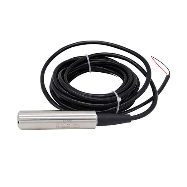
Wide voltage power input 10~30V is acceptable. When wiring the 485 signal line, pay attention that the A/B lines cannot be connected in reverse, and the addresses of multiple devices on the bus cannot conflict.
It is mainly used for non-contact flow measurement in open channels, rivers, irrigation areas, underground drainage networks, flood prevention and early warning, etc.
If the radar flow meter cannot receive a signal or the signal is weak, it may be due to antenna damage, poor connection or signal interference. At this time, you can check whether the antenna is intact, confirm whether the connection is tight, and try to change the installation position to avoid interference sources.
The large measurement deviation of the radar flow meter may be due to unstable fluid state, scaling of the inner wall of the pipeline, sensor position offset and other reasons. To solve this problem, it is necessary to regularly check the pipeline state, clean the inner wall, and ensure the correct position of the sensor. At the same time, the measurement deviation can be reduced by taking the average value of multi-point measurements.
Zero drift is a common problem of radar flow meter, which may be caused by temperature changes, mechanical wear or circuit aging. To solve this problem, the flowmeter needs to be calibrated regularly to ensure its accuracy. In addition, the impact of zero drift can be reduced by software compensation or hardware adjustment.
The large gap in the radar flow meter data may be due to bubbles, impurities or electromagnetic interference in the fluid. At this time, you can install a filter or take other measures to eliminate the interference. At the same time, you can improve data stability by optimizing the algorithm or increasing the sampling frequency.
Related Blogs
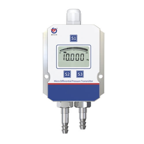
Table of Contents What is differential pressure? Differential pressure is the difference between the values of the pressures at different
Table of Contents The dew point depends on how much water vapor is present in the air. If the air
Table of Contents What is a vibration sensor? Vibration sensor is a device that measure the vibration speed and frequency
Long-term rainfall and melting snow have raised water levels and flooded city roads, causing flooding. Frequent and extreme flooding is
Natural disasters such as floods and heavy rains pose threats to lives and property around the world. Without a proper
Table of Contents Water is the source of life, integral to every aspect of human production and daily living. In
Table of Contents Have you or your friend experienced a broken water pipe, water accumulation in the kitchen or bathroom?