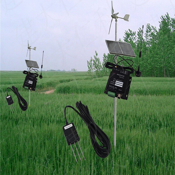
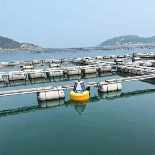
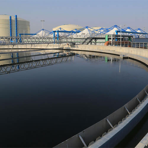
what is a soil moisture sensor?
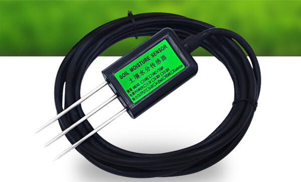
The soil moisture sensor is composed of a stainless steel probe and a waterproof probe, which can be buried in the soil and dams for a long time to conduct fixed-point monitoring and online measurement of the surface and deep soil moisture. Used in conjunction with a data collector, it can be used as a tool for fixed-point moisture monitoring or mobile measurement.
Soil moisture sensor working principle
Drying method
The drying method is an extremely common method for measuring soil moisture and is also a standard method. Specifically: Obtain a certain amount of soil from the field, then put it in an oven at 105°C and wait for it to dry. The standard of drying is that the weighing is constant before and after twice. The moisture lost after drying is the moisture content of the soil. The calculation formula is soil moisture content=W/M*100%, M is the weight of soil before drying, and W is the weight of soil moisture, that is, the difference between M and the weight of soil after drying M’.
Resistance method
The resistance method uses the resistance of gypsum, nylon, glass fiber, etc., and their water content. When these intermediates plus electrodes are placed in moist soil, and then after a while, the water content of these things reaches equilibrium. Due to the relationship between resistance and moisture content, we have previously calibrated a certain correspondence between resistance and percentage, and then we can use these components to obtain moisture readings within the suction range of 1 to 15 atmospheres.
The value measured by the drying method is accurate, but it has the disadvantage of poor real-time performance. If we want to measure quickly, we can consider the soil temperature and humidity sensor. The soil temperature and humidity sensor time-domain reflectometry (TDR) or high-frequency oscillation method (FDR) two monitoring principles can provide more accurate soil moisture content in real-time.
TDR method
The Chinese name of TDR is Time Domain Reflectometry, which is a soil moisture measurement method developed in the 1980s. This method is very common in foreign countries. In China, it has only been introduced in recent years, but it was immediately paid attention to by various departments after its introduction. TDR time domain transmission is a common way to quickly monitor soil moisture. The principle is that the waveform on a mismatched transmission line will be transmitted. The waveform at any point on the transmission line is the superposition of the original waveform and the transmitted waveform. The response time of TDR principle equipment is about 10-20 seconds, which is suitable for mobile measurement and fixed-point monitoring.
TDR has strong independence, and its results are not affected by environmental factors such as soil type, density, and temperature. Besides, there is another important point: TDR can measure soil moisture under the icing, which is unmatched by other methods. Besides, TDR can simultaneously monitor the soil water and salt content, and there is almost no difference between the results of the two measurements. The accuracy of this measurement method is evident.
FDR method
The Chinese name of the FDR method is the high-frequency oscillation method, and the birth time of FDR is slightly later than TDR. At first, because TDR equipment was expensive, foreign companies such as AquaSPY and Sentek developed FDR to find a simpler method than TDR to measure the dielectric constant of soil. FDR is not only cheaper than TDR but also has a shorter measurement time. After a specific soil calibration, the measurement accuracy is high, and the shape of the probe is not limited, and multiple depths can be measured at the same time, and data acquisition is easier to achieve.
The FDR method uses the working principle of electromagnetic pulse, and measures the apparent permittivity of the soil according to the frequency of electromagnetic wave propagation in the medium, thereby obtaining the soil volumetric water content. Renke soil moisture sensor adopts the FDR principle and has higher accuracy.
Soil moisture sensor wiring and calculation
RS485 output signal
The wide voltage power input is 5~24V. When wiring the 485 signal line, pay attention to the two wires A/B not to be reversed, and the addresses of multiple devices on the bus must not conflict.
| Line color | Description | Remarks |
|---|---|---|
| Red | power supply positive | 5~24V DC |
| Black | power ground | GND |
| Yellow | 485-A | 485-A |
| White | 485-B | 485-B |
| Green (shield layer) | Connect the negative pole of the power supply to the acquisition mode, and connect the positive pole of the power supply to the setting mode | |

Using Modbus-RTU communication protocol, the format is as follows:
Initial structure ≥ 4 bytes time
Address code = 1 byte
Function code = 1 byte
Data area = N bytes
Error check = 16-bit CRC code
Time to end structure ≥ 4 bytes
Address code: the address of the transmitter, which is unique in the communication network (factory default 0x01).
Function code: the command function instruction issued by the host, this transmitter only uses function code 0x03 (read register data).
Data area: The data area is the specific communication data, pay attention to the high byte of 16bits data first!
CRC code: two-byte check code.
Host query frame structure
| address code | function code | Register start address | Register length | Check code low bit | Check code high |
|---|---|---|---|---|---|
| 1 byte | 1 byte | 2 byte | 2 byte | 1 byte | 1 byte |
Slave response frame structure
| address code | function code | Effective bytes | Data area | Second data area | Nth data area | Check code |
| 1 byte | 1 byte | 1 byte | 2 byte | 2 byte | 2 byte | 2 byte |
Register address
| Register address | PLC or configuration address | Content | Operation | Definition description |
| 0001 H | 40002 | Moisture content | Read-only | Uploaded data is 100 times the actual value |
Communication protocol example and explanation
Read the moisture value of the device address 0x01
Interrogation frame
| address code | function code | starting address | Data length | Check code low bit | Check code high |
| 0x01 | 0x03 | 0x00 0x01 | 0x00 0x01 | 0xD5 | 0xCA |
Response frame (for example, the moisture value read is 38.85%)
| address code | function code | Number of bytes | Moisture value | Check code low bit | Check code high |
| 0x01 | 0x03 | 0x02 | 0x0F 0x2D | 0x7D | 0xA9 |
Moisture value:
0x0F2D (hexadecimal) = 3885 => moisture value = 38.85%
Analog output signal
| Line color | Description | Remarks |
|---|---|---|
| Red | Power is positive | 12~30V DC |
| Black | Power negative, moisture signal negative | GND |
| Brown | moisture signal positive | To the ground |
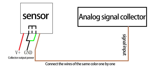
Calculation method
Current output signal conversion calculation
For example, the range 0~100%, 4~20mA output, when the output signal is 12mA, calculate the current moisture value. The span of this moisture range is 100 degrees, expressed by a 16mA current signal, 100%/16mA=6.25%/mA, that is, current 1mA generation
The surface moisture changed by 6.25%. Measured value 12mA-4mA=8mA., 8mA*6.25%/mA=50%. The current moisture value is 50%.
Voltage output signal conversion calculation
For example, the range 0~100%, 0~10V output, when the output signal is 5V, calculate the current moisture value. The span of this moisture range is 100 degrees, expressed by a 10V current signal, 100%/10V=10%/V, that is, voltage 1V represents moisture change
10%. The measured value 5V-0V=5V, 5V*10%/V=50%. The current moisture value is 50%.

