
Where to mount wind sensor?
Installing wind sensor on the weather station
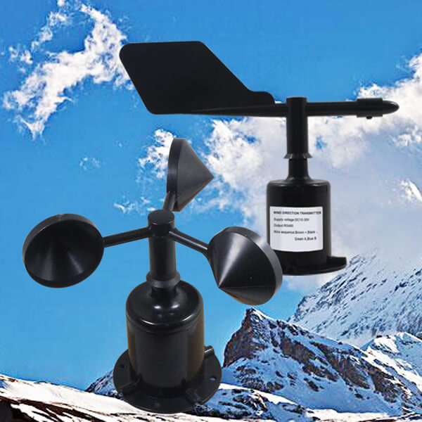
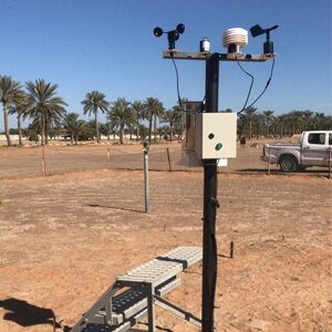
The wind sensor is a crucial component of a weather station, providing users with real-time wind speed and direction data. The height and angle at which the wind sensor is installed can affect the accuracy of the measurements. Therefore, properly installing the wind speed and direction sensor is an essential skill for weather station enthusiasts.
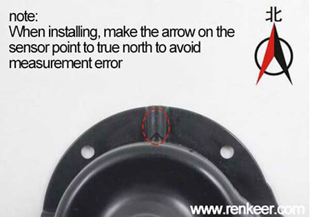
Firstly, when installing a wind sensor in a weather station, it should be placed in an area away from buildings, trees, walls, and other obstacles to avoid interference from localized airflow. For localized studies or small-scale applications, the wind speed and direction sensors should be installed vertically on a horizontal arm at a height of 3-5 meters above the ground. The distance between the wind speed sensor and the wind direction sensor should be no less than 0.5 meters, meaning they should be installed on opposite sides of the horizontal arm. This effectively prevents interference between the sensors. The wind sensor must be leveled using a spirit level to avoid measurement errors caused by tilting. Additionally, the wind direction sensor should be calibrated with a compass or GPS to ensure it points to the true geographic north (not magnetic north).
The wind speed and direction sensors are fixed to the weather station using flange mounting. The threaded flange connection ensures that the lower part of the wind sensor is securely fastened to the flange plate. The base has a diameter of 80mm, with four mounting holes of Ø4.5mm drilled on a Ø68mm circle. Bolts are used to tightly secure the sensor to the horizontal arm. Flange connections are convenient to use and can withstand significant pressure.
Installing wind sensor on the building
When installing the wind sensor in an area with numerous surrounding buildings, how should the installation location be chosen? In such cases, it is common to install the wind speed and direction sensors on the rooftop. To ensure more accurate measurement results, the sensors should be installed at least 3 meters above the rooftop.
You can first secure the wind sensor with bolts onto two stainless steel brackets, then attach the brackets to both sides of a sufficiently tall mast. This ensures that the wind speed and direction sensors are installed higher than the building’s roof, minimizing the interference caused by nearby structures.
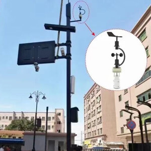
If a suitable mast is not available, you can opt for a 3 meters bracket, securing it vertically on the rooftop and installing the wind speed and direction sensors at the top. This way, the wind sensors are effectively mounted on the rooftop.
Just like with the selection of the weather station location, wind sensors installed on buildings also need to avoid obstructions. Choose a location free from chimneys, air conditioning units, or other equipment that may disrupt airflow. Additionally, place the sensors on the upwind side of the building (the prevailing wind typically blows from this side) to ensure clean and undisturbed airflow for accurate measurements.
Installing wind sensor on boat
Thanks to the convenience offered by IoT technology, the safety of the maritime industry has been significantly improved, allowing crew members to access reliable meteorological information through various instruments. For instance, by installing marine wind speed sensors on the ship, the crew can stay inside the cabin and monitor the wind conditions outside, ensuring both safety and accuracy.
The height of the mast on large ships is typically about 15 meters above sea level. Wind speed sensors are usually installed on both sides of the mast, with one placed 4 meters from the mast’s left arm (relative to the direction of the ship’s bow), and the other mounted at the top of the mast where there is no obstruction. With ongoing technological advancements, modern maritime technology now utilizes ultrasonic wind speed and direction sensors to avoid magnetic interference. These sensors are unaffected by magnetic fields and are easy to install.
The installation location and requirements for wind sensors vary depending on the type and purpose of the ship (such as cargo ships, research vessels, yachts, etc.). Wind sensors should not be installed in areas where airflow may be disrupted by the ship’s structure, chimneys, vents, or other obstructions, and they must be installed horizontally. Since ships operate in environments with significant vibrations, it is important to consider anti-vibration measures during installation to ensure the stability of the sensors and accurate data collection.
How to mount wind sensor?
Tool materials: wind speed sensor, mounting screws, USB to 485 converter, 485 terminal resistance.
Interface Description: Wide-voltage power input can be 10~30V. 485 When wiring the signal line, pay attention to the A\B two lines can not be reversed, and the addresses of multiple devices on the bus can not conflict.
Electrical wiring instructions
| Thread color | Description | |
|---|---|---|
| Power supply | brown | Power is positive |
| black | Power negative | |
| Communication | green | 485-A |
| blue | 485-B |
Field wiring instructions: When multiple 485-type devices are connected to the same bus, there are certain requirements for on-site wiring, which should be connected according to the 485 wiring manual.
Analog type
The output types for analog signals are 4-20mA, 0-5V, and 0-10V. The power supply is 10~30V DC input. For the 0-10V output type, only a 24V power supply can be used. It is also compatible with both three-wire and four-wire configurations. The three-wire connection: the brown wire connects to the positive power supply, the black and yellow wires connect to the negative power supply, and the blue wire connects to the signal input. The four-wire connection: the brown wire connects to the positive power supply, the black wire connects to the negative power supply, the blue wire connects to the positive wind speed signal, and the yellow wire connects to the negative wind speed signal.
RS485 type
Materials: wind direction sensor, mounting screws, USB to 485, 485 terminal resistance.
Interface Description: Wide-voltage power input can be 10~30V. 485 When wiring the signal wire, pay attention to A\B The two wires cannot be connected reversely. Addresses between two devices cannot conflict.
Electrical wiring
| Thread color | Description | |
|---|---|---|
| Power supply | brown | Power is positive |
| black | Power negative | |
| Communication | green | 485-A |
| blue | 485-B |
Field wiring instructions: When multiple 485 devices are connected to the same bus, there are certain requirements for on-site wiring, and the wiring is by the 485 modes.
Analog type
The output types for the wind direction sensor’s analog signals are also 4-20mA, 0-5V, and 0-10V. The power supply is 10~30V DC input. For the 0-10V output type, only a 24V power supply can be used. It is also compatible with both three-wire and four-wire configurations. The three-wire connection: the brown wire connects to the positive power supply, the black and yellow wires connect to the negative power supply, and the blue wire connects to the signal input. The four-wire connection: the brown wire connects to the positive power supply, the black wire connects to the negative power supply, the blue wire connects to the positive wind direction signal, and the yellow wire connects to the negative wind direction signal.
Wind sensor installation precautions
1. Do not disassemble by yourself, let alone touch the sensor core, to avoid damage to the wind sensor.
2. Keep away from high-power interference equipment as much as possible to avoid inaccurate measurements, such as inverters and motors. The power supply must be disconnected when installing or disassembling the transmitter. Water in the sensor may cause irreversible changes.
3. Prevent chemical reagents, oil, dust, etc. from directly invading the sensor, do not use it for a long time under condensation and extreme temperature environments, and strictly prevent thermal shock.